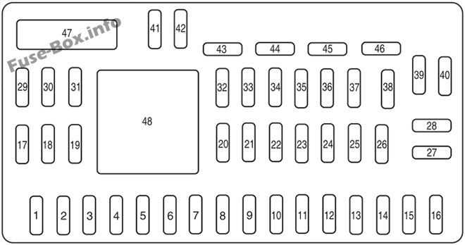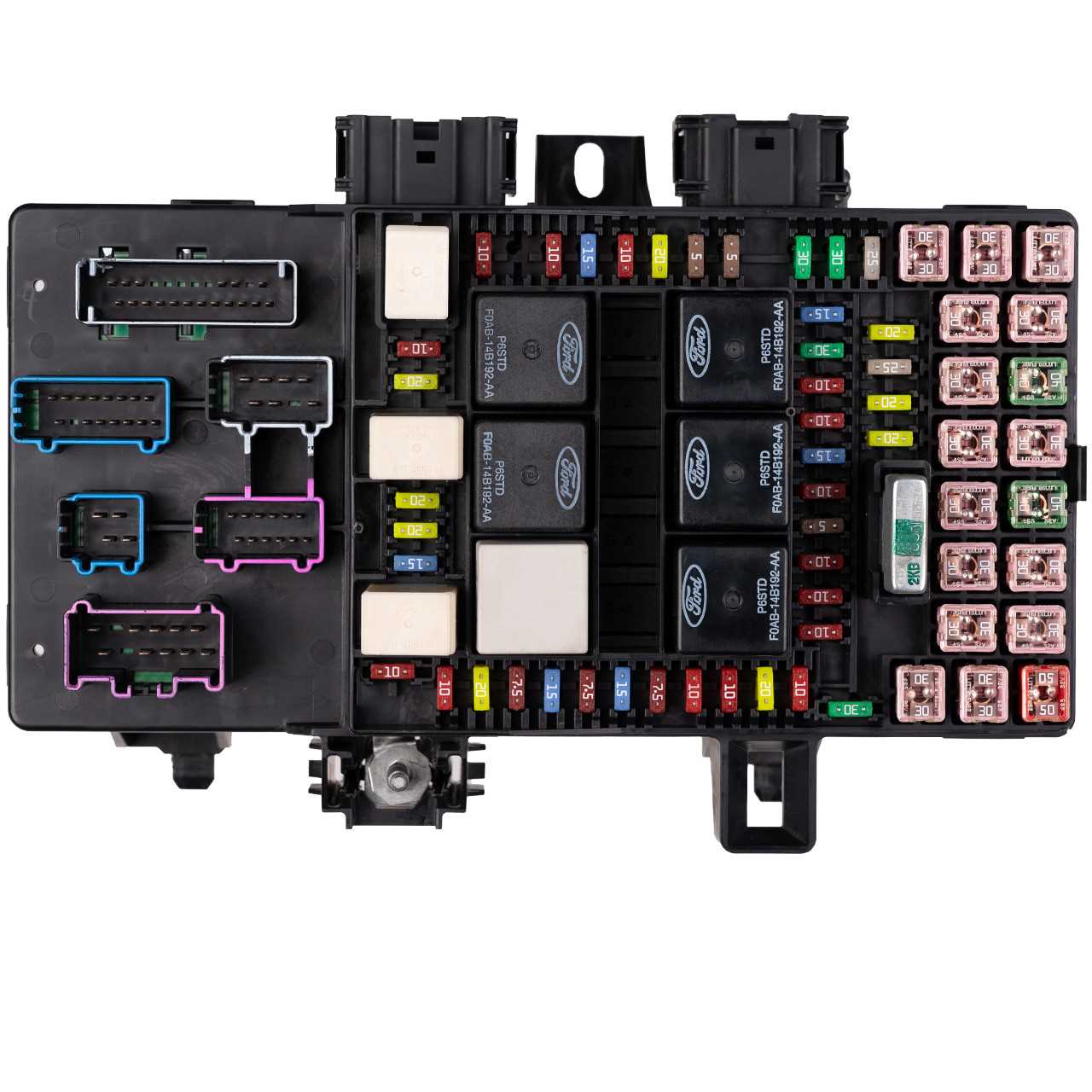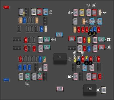
Understanding the layout and connections of a vehicle’s electrical system is essential for anyone looking to troubleshoot or make adjustments to various elements within the car. This section provides a comprehensive explanation of the key systems that control power distribution and ensure smooth operation of the vehicle’s internal components. It aims to clarify how these elements are interconnected and what role each one plays in the overall function of the car.
The detailed configuration of the internal electrical pathways can help prevent potential issues by enabling quick identification of key areas. Whether you’re addressing minor electrical concerns or preparing for a more complex adjustment, having a clear understanding of how power is routed and controlled is critical. The layout presented here will guide you through the essential elements involved in powering the various systems within the vehicle.
In this guide, we will explore the vital aspects of your vehicle’s electrical circuits, focusing on areas where energy is directed and distributed to support crucial features and accessories. This information can assist you in performing repairs or modifications with confidence, helping to maintain the vehicle’s reliability and safety.
2010 Ford F150 Fuse Box Overview
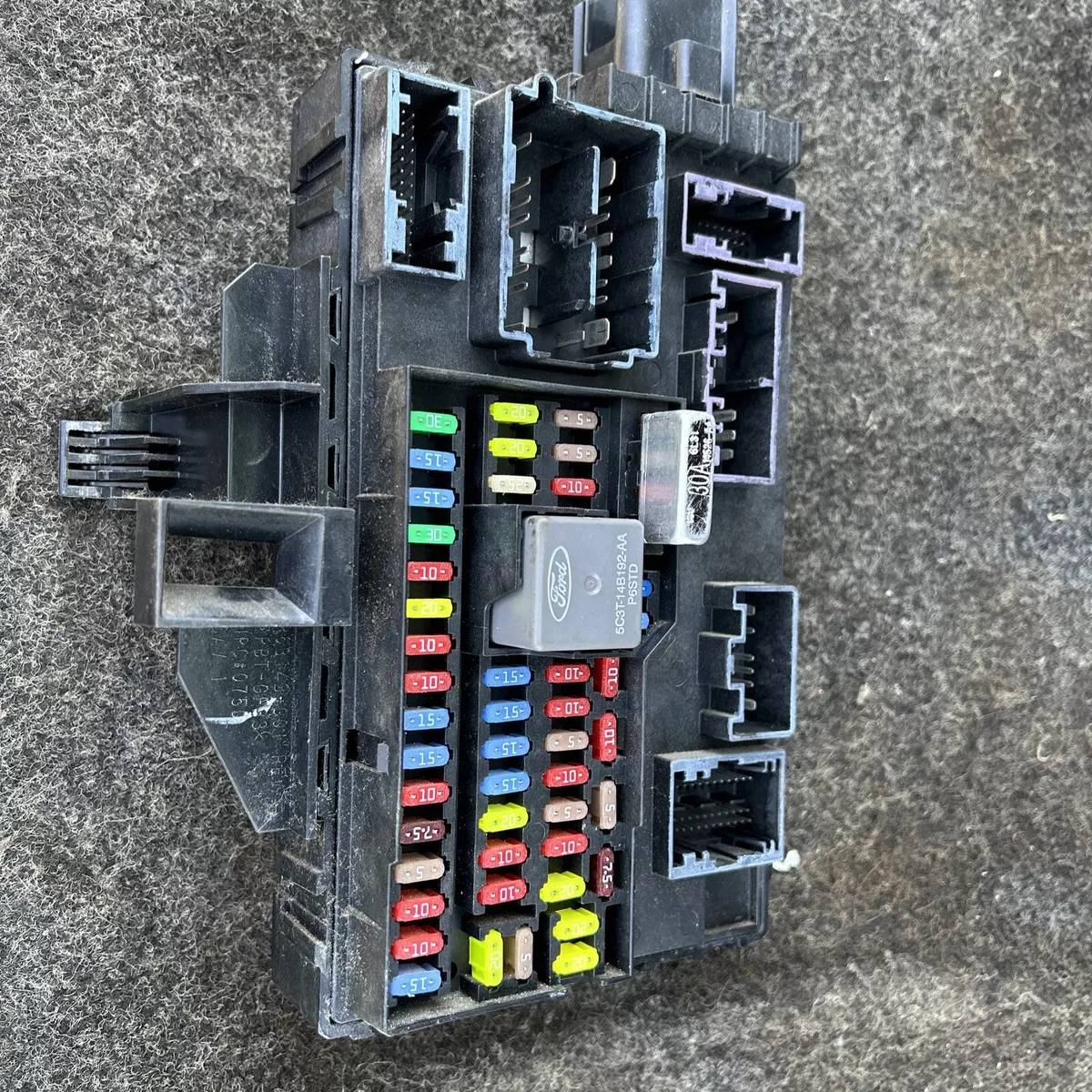
The electrical system in vehicles is designed to distribute power efficiently to various components. A central unit helps regulate this flow of electricity, ensuring that different systems receive the energy needed to function correctly. This section provides insights into the layout and the key features of this critical component, as well as its purpose in managing electrical circuits.
Main Functions

This centralized unit is responsible for safeguarding the electrical components by controlling the flow of current. If an overload or short circuit occurs, this unit isolates the affected section, preventing damage to the rest of the system. This makes it a vital safety feature in any vehicle.
Component Layout
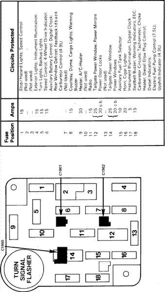
The unit is divided into several sections, each dedicated to different parts of the vehicle’s electrical network. Below is a table summarizing the key sections and their corresponding systems:
| Section | Controlled Systems |
|---|---|
| Engine Compartment | Ignition, Headlights, Air Conditioning |
| Cabin Area | Interior Lights, Audio System, Power Windows |
| Auxiliary Components | Tow Package, Auxiliary Power Outlets, Trailer Lights |
Understanding the Layout and Functions of Fuses

Electrical systems in modern vehicles rely on various safety components to ensure optimal performance and protection from potential electrical issues. Among these components, protective elements play a critical role in preventing circuits from overloading or shorting, helping to safeguard essential functions. By understanding how these components are arranged and what roles they perform, vehicle owners can troubleshoot common electrical problems with ease.
Placement of Protective Components
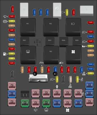
These safety devices are typically grouped together in a central location within the vehicle. Their specific positions vary based on the system they protect, such as lighting, power accessories, or engine control systems. The grouping is designed for easy identification and access, allowing for quick replacement or inspection when necessary.
Key Functions of Circuit Protectors
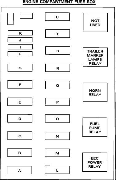
Each individual component serves a specific purpose, corresponding to a different part of the vehicle’s electrical framework. Some protect high-demand systems like climate control, while others manage smaller but equally important tasks like interior lighting or charging outlets. Knowing the function of each helps in diagnosing issues related to malfunctioning electronics or power failures.
| System | Role of the Component | |||||||||||||
|---|---|---|---|---|---|---|---|---|---|---|---|---|---|---|
| Lighting System | Ensures headlights, taillights, and interior lights function safely. | |||||||||||||
| Power Accessories | Manages components like windows, locks, and mirrors. | |||||||||||||
| Engine Control | Protects the system responsible for engine performance and emissions. |
| System | Location | Part Number | ||||||||||||
|---|---|---|---|---|---|---|---|---|---|---|---|---|---|---|
| Headlights | Driver-side panel | 15A | ||||||||||||
| AC System | Engine compartment | 30A | ||||||||||||
Step-by-Step Guide to Access the Fuse Box
Gaining access to the electrical component housing is crucial for troubleshooting and ensuring your vehicle runs smoothly. This guide outlines a systematic approach to reach the compartment safely and efficiently, allowing you to check connections and replace any necessary elements. Follow these steps to easily locate and open the compartment:
Common Fuse Issues and Troubleshooting for Ford F150Electrical systems in vehicles are vital for ensuring optimal performance and safety. However, various complications may arise due to the failure of protective elements responsible for controlling power flow. Understanding typical problems and how to address them can save time and enhance the longevity of the vehicle’s electrical components.
When faced with electrical difficulties, follow these troubleshooting steps:
Regular maintenance and timely inspections can prevent many of these common electrical issues, ensuring the vehicle operates smoothly and reliably. |
